44 ids 805 alarm wiring diagram
The information in this document is subject to change without notice. No part of this document may be reproduced or transmitted in any form or by any means, electronic or mechanical, for any purpose, without IDS 800 INSTALLER MANUAL; IDS 805 INSTALLER MANUAL; IDS 816 INSTALLER MANUAL; Installations. Arm & Disarm alarm remotely; Electric Fence & C.O.C; 8 to 32 Zone Control Panels; 16 to 256 Zone Control Panels; IDS Alarm Equipment; Paradox Alarm Equipment; Contact Us. Complete a holiday form; Order the SMS Service; Talk 2 Us; Update Client Key ...
IDS X64 Installer Manual 700-398-02D Issued August 2010 10 1. Introduction to the IDS X64 Thank you for purchasing an IDS Alarm Panel. The IDS X64 is a versatile, Bylaw 25 compliant, expandable Alarm Panel. It has up to 8 partitions and can be expanded from 8-64 zones. Most features are configurable and may be programmed directly through
Ids 805 alarm wiring diagram
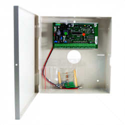
Diagram#1 Diagram#2 6.2LEDIndications 6.2.1 CHG-Chargeindicator(RED) 6.2.2SYS-Systemindicator(BLUE) Status Description ConstantON NoSIMCard(or)NoNetworkReception OFF VehicleParked-ACCPowerOFF Quickflash NormalWorkingMode 6.2.3GPS-GPSindicator(GREEN) 6.3DeviceButtonInstruction Button Description Status Description ConstantON CurrentlyCharging OFF Introduction to the IDS 805 The IDS 805 is a versatile, state of the art, microprocessor based, eight-zone Alarm Panel. Most features are optional and may be programmed either directly through the keypad or via the telephone system, using the IDS download software and appropriate modem. IDS800 INSTALLER MANUAL 1. Introduction to the IDS800 The IDS800 is a versatile, state of the art, microprocessor based, eight zone alarm panel. Most features are optional and may be programmed either directly through the keypad or via the telephone system, using the IDS download software and appropriate modem. Page 6: Installation And Wiring
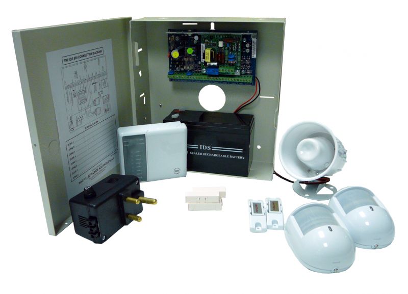
Ids 805 alarm wiring diagram. Ids x64 wiring diagram. The ids x64 is a versatile bylaw 25 compliant expandable alarm panel. The kick start jumper must be in circuit when using only a battery ie. View and download ids x64 installer manual online. Connection diagram without tamper per zone and familiarise yourself with the following sections. all alarm detection devices, keypads and other modules are to be located. 2: Mounting the Panel The control panel should be mounted in a dry area close to an unswitched AC power source and the incoming telephone line. ! You must complete all wiring before connecting the !! 2). " R 2,732.4015% VAT incl. IDS805 Core Kit. Small wired alarm system with all the basics to start of with. Kit Includes: 1 x IDS 805 Control panel - max 8 zones. 1 x 8 Zone Led Keypad. 2 x Optex RX Core indoor Passives. Introduction Selection guide 4 Measuring principles, accuracy 14 Mechanical design types and mounting Rotary encoders with stator coupling 16 Rotary encoders for separate shaft coupling 19 Shaft couplings 24 General mechanical information 27 Safety-related position measuring systems 30 Specifi cations Absolute rotary encoders Incremental rotary encoders
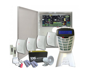
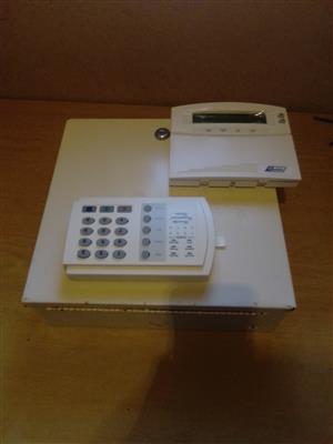
The IDS 805 Alarm system is the most popular alarm system at an incredible R3500, INSTALLATION INCLUDED. The IDS 805 is a fully featured 8 zone security system that provides immediate notification of burglary, fire, medical & panic conditions. MultiTransmitter User Manual. Updated October 4, 2021. MultiTransmitter is an integration module with 18 wired zones for connecting third-party detectors to the Ajax security system. To protect against dismantling, MultiTransmitter is equipped with two tampers. It is powered from the mains 100-240 V AC, and can also run on a 12 V backup battery. Wiring Code Identification Information WIRE CODE IDENTIFICATION Each wire shown in the diagrams contains a code (Fig. 1) which identifies the main circuit, part of the main circuit, gauge of wire, and color. The color is shown as a two-letter code, which can be identified by referring to the Wire Color Code Chart (Fig. 2). IDS 805 Installer Manual 700-266-02H Issued September 2009 1. 11.. 1. IntroductiIntroduction to the Introduction to the IDS 805on to the IDS 805IDS 805 The IDS 805 is a versatile, state of the art, microprocessor based, eight-zone Alarm Panel. Most features
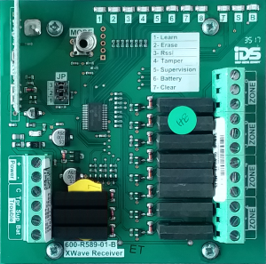
The IDS X64 Remote Receiver is a 433.92 MHz RF receiver that is designed to connect to an IDS X64 Alarm Panel. The receiver connects to the keypad Bus (via D+ and D- terminals), permitting the Alarm Panel to be armed and disarmed from Remote Transmitters. When remotes are learnt, they are assigned to USER CODES stored in the IDS Alarm Panel. Description : Burglar Alarm Wiring Diagram pertaining to Burglar Alarm Wiring Diagram Pdf, image size 864 X 672 px, and to view image details please click the image. Here is a picture gallery about burglar alarm wiring diagram pdf complete with the description of the image, please find the image you need. So the alarm is actually triggered when the current completes the loop, not when it's stopped. This is very commonly used for smoke detectors, but it can also be used in other specialized instances. And it's pretty common to wire more than one smoke detector together into a zone. To do this, you'll actually wire in parallel instead of series. Linear Guides. Linear Scales. Servo Motor. Built-In Rotary. 1-Degree Rotary. 5-Degree Rotary. Full 4th Degree Rotary. Casting. Chip Removal.
1 IDS 805 Installer Manual 700-266-02H Issued September 2009
Download >> Download Ids 805 remote receiver manual Read Online >> Read Online Ids 805 remote receiver manual ids x64 wiring diagram ids 805 gsm module alarm remote receiver how to program a house alarm remoteids 805 sms module ids 1 channel receiver manual ids 816 bus receiver manual ids x64 user manual. 1. IDS 805 Installer Manual 700-266-02H Issued September 2009 ..
House alarm reset?
Read Free Ids 805 Quick Install Manual Ids 805 Quick Install Manual ... system wiring diagram TIVDIO Keypad RFID Access Control ... Publisher How to design student IDS DSC PowerSeries Neo Alarm System Wiring Instructions - How you can be successfulIds 805 Quick Install Manual

Category: Control Panels
How to set the zone types and partitions on the IDS X-Series LCD alarm keypad. How to set the zone types and partitions on the IDS X-Series LCD alarm keypad.

IDS 805 8 ZONE CONTROL PANEL-INCL 30VA TFR WITH DIALLER ...
Alarm 805 LOW SPINDLE LUBRICATION. The reservoir oil level is low. Refill the reservoir. The oil level sensor is faulty. Test the oil level sensor. Hot, Noisy, or Failed Spindle. The reservoir is filled with the incorrect oil type. Refill the reservoir. There are leaks in the fittings. Inspect the fittings for leaks. The lubrication tube is ...

Training Manual. Installer Training 805 Stock Code: B08-MN ...
IDS 805.The IDS 805 is a versatile, state of the art, microprocessor based, eight-zone Alarm Panel. Most features are optional and may be programmed either directly This Pin was discovered by Julia Van. Discover (and save) your own Pins on Pinterest. IDS 805 Quick User Manual 700-266-07A Issued January 2015.
IDS 805 Alarm Starter Kit | Established Security - IDS 85 For ...
A tamper circuit detects an intruder interfering with alarm system wiring even when it is not armed. ... New sensors are normally "added" to an alarm system after they are physically installed and the panel IDs the device so that it can subsequently read its alarm status. ... but often a wiring diagram comes with the sounder showing how it ...

IDS 805
Test your Page You must be logged in to run a page validation test. Click to login. Reprocess You must be logged in and a Protection Pro member to do manual rescans. Click to login.For more info visit the FAQ. Delete You must be logged in and a Protection Pro member to do manual deletions. Click to login.For more info visit the FAQ. Auth Key Certificate unique auth key is:
IDS 805 full kit
Burglar Alarm Circuit. electronics. By Jayant Dec 12, 2015 15. Burglar alarm system is an important part of home security systems. This burglar alarm project is based on PIR sensor, UM3561 and Speaker. PIR sensor used to detect body motion and UM3561 & speaker to produce Police siren after any movement detection.

suneducationgroup.com Toys & Games Receivers & Transmitters ...
How to wire tamper zones on your IDS X64 and 805 alarm system. How to wire tamper zones on your IDS X64 and 805 alarm system.
IDS x64 Alarm Expert
Radio Shack by Product Types. To locate your free Radio Shack manual, choose a product type below. Showing Product Types 1 - 50 of 146. #.
POWERSCAN MANUAL
Windhoek Tel: +264 61 234 015 Fax: +264 61 234 184 Email: sales1@namibiasecuritysupplies.com
IDS
IDS800 INSTALLER MANUAL 1. Introduction to the IDS800 The IDS800 is a versatile, state of the art, microprocessor based, eight zone alarm panel. Most features are optional and may be programmed either directly through the keypad or via the telephone system, using the IDS download software and appropriate modem. Page 6: Installation And Wiring

Smart Sensors and Applications Student Guide Datasheet by ...
Introduction to the IDS 805 The IDS 805 is a versatile, state of the art, microprocessor based, eight-zone Alarm Panel. Most features are optional and may be programmed either directly through the keypad or via the telephone system, using the IDS download software and appropriate modem.
Addressable Fire Alarm System 4 Zones Fire Alarm Control Panel - Buy Fire Alarm Control Panel,Alarm System Siren Control Panel,Fire Alarm Control ...
Diagram#1 Diagram#2 6.2LEDIndications 6.2.1 CHG-Chargeindicator(RED) 6.2.2SYS-Systemindicator(BLUE) Status Description ConstantON NoSIMCard(or)NoNetworkReception OFF VehicleParked-ACCPowerOFF Quickflash NormalWorkingMode 6.2.3GPS-GPSindicator(GREEN) 6.3DeviceButtonInstruction Button Description Status Description ConstantON CurrentlyCharging OFF
Alarms For Sale in South Africa | Junk Mail
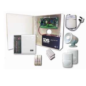
IDS 805 Alarm System Kit

IDS 805 TRAINING MANUAL Pdf Download | ManualsLib

IDS 805 Installer Manual 700-266-02H Issued … / ids-805 ...
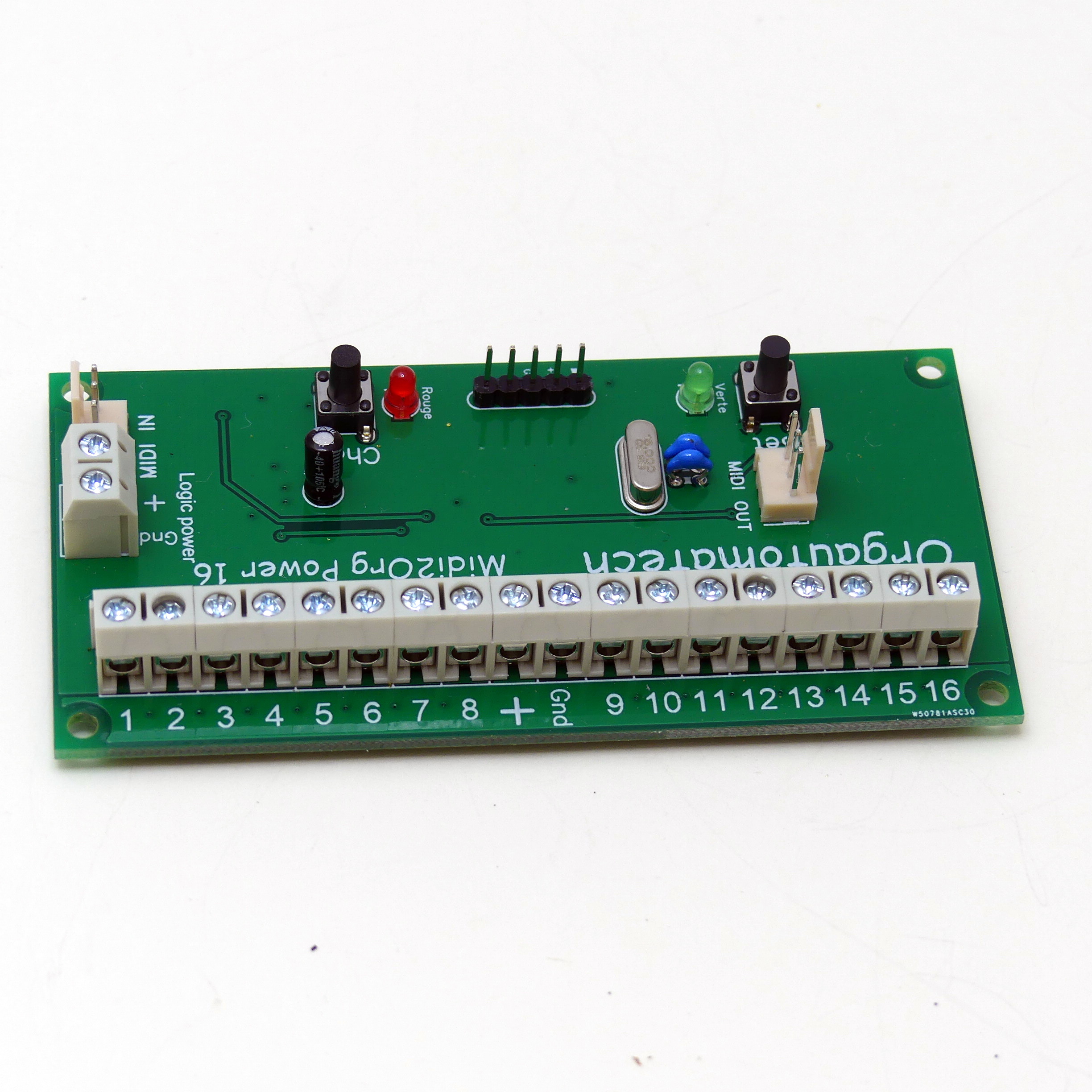
Midi2Org 16 Power - Orgautomatech
Alarm System | JVA PH
Untitled

Training Manual. Installer Training 805 Stock Code: B08-MN ...
IDS x64 Alarm Expert

How to wire tamper zones on your IDS X64, 805 and 806 alarm system
Training Manual

Alarms in South Africa | Junk Mail
EXPANDABLE PANEL RANGE

IDS 805 Alarm Kit
1 IDS 805 Installer Manual 700-266-02H Issued September 2009

IDS 805 DUO SMS

ialarm.eu - www.iAlarm.eu, Denn sicher ist sicher!...
1 IDS 805 Installer Manual 700-266-02H Issued September 2009

Hitachi ZW370-5B Hydraulic Circuit Diagram - PDF DOWNLOAD by ...

IDS X64 8-ZONE PLUG-IN EXPANDER | กล้องวงจรปิด และ สัญญาณกันขโมย

SCHMERSAL BOHNKE + PARTNER bp308 Manual Instalasi - Manual +
Untitled

IDS805 Alarm System - Alarm System Products

Видео alarm wiring
Application Note–Backup Interface Installation Best Practices
Africa's leading manufacturer and distributor of electronic ...
U-Prox IP400

PrismTech (@dawayira) / Twitter
Online Shop
0 Response to "44 ids 805 alarm wiring diagram"
Post a Comment