40 icm controls umsr-50 wiring diagram
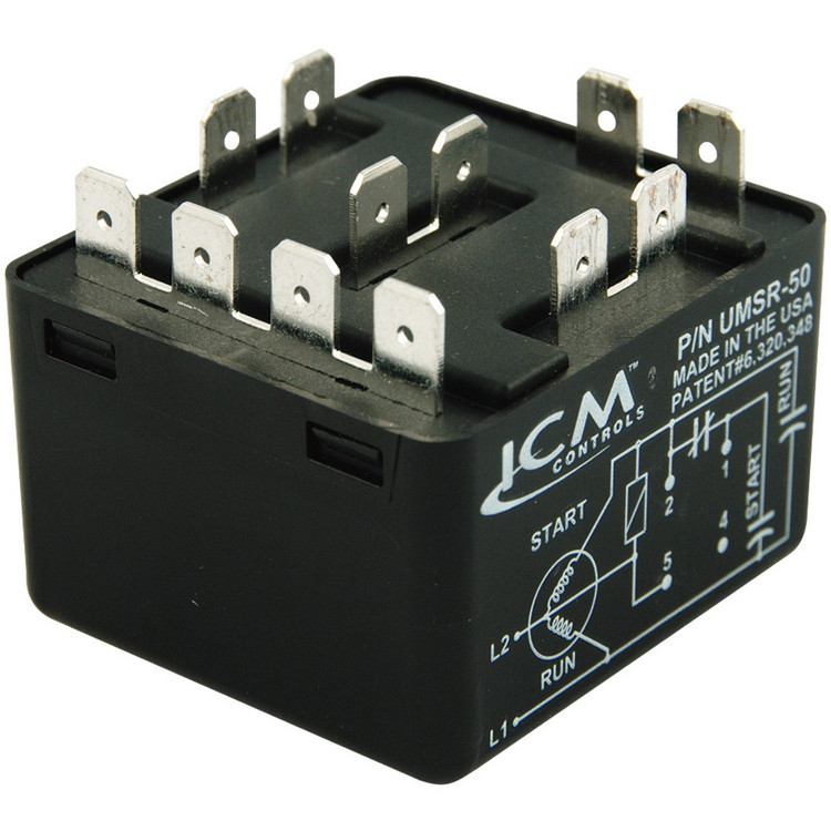
ICM UMSR-50 UNIVERSAL MOTOR STARTING RELAY WIRING DIAGRAM SPECIFICATIONS Standard Wiring Diagram Alternative Reduced Arcing Configuration Input: – Voltage Rating: 110-270 VAC, Single Phase – Maximum Voltage Contact Rating: 502 VAC 5(absolute) Motor Power Rating: Up to 10 HP Operating Position: Non-positional Safety Time Out: <2-seconds Consumption: 5VA max. Insulation: Class B (130°C ... umsr 50, phase failure relays steven engineering, automotive diagrams page 64 circuit wiring diagrams, universal motor starting relay series umsr amazon s3, contactors motor starters and motor relays for electrical, 800 2 0 typical wiring diagrams for push button control, universal motor starting relay icm controls, instruction sheet rbm wiring ...
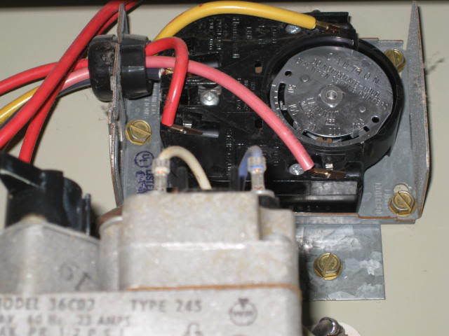
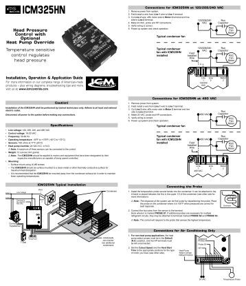
The control must be secured to an area that will experience a minimum of vibration and remain below the maximum ambient temperature rating of 175°FThe control is appro . ved for minimum ambient temperatures of -40°F. Any orientation is acceptable. Refer to the wiring diagram and wiring table when connecting

Icm controls umsr-50 wiring diagram
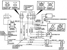
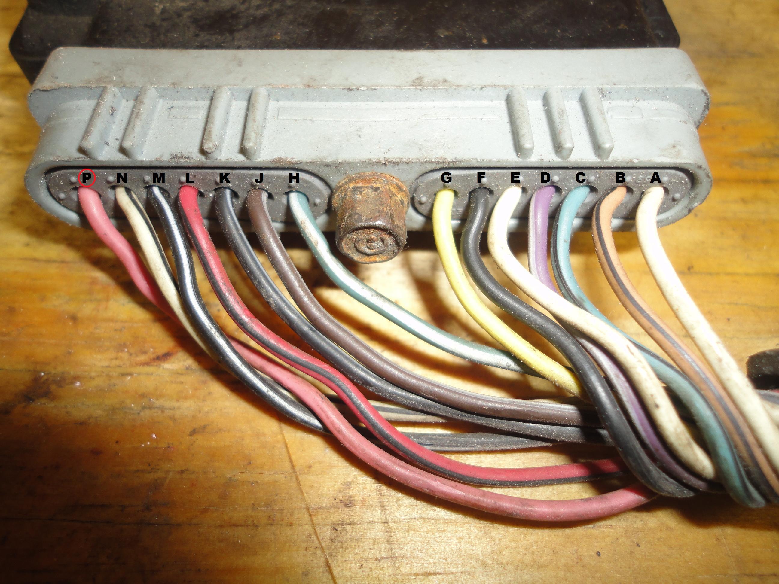
ICM UMSR-50 UNIVERSAL MOTOR STARTING RELAY www.icmcontrols.com LII332 ICM CONTROLS 7313 William Barry Blvd. 800-365-5525 North Syracuse, NY 13212 WIRING DIAGRAM SPECIFICATIONS Standard Wiring Diagram Alternative Reduced Arcing Configuration Input: – Voltage Rating: 110-270 VAC, Single Phase – Maximum Voltage Contact Rating: 502 VAC (absolute) Motor Power Rating: Up to 10 HP Operating ... Pump Portable. Motor JIANGNAN YIFAN MOTOR CO LTD FORMER WUXI JIANGNAN. ICM Controls UMSR 50 Universal Motor Starting Relay 50. L6235 three phase brushless DC motor driver. Electric motor Wikipedia. Synchronous motor SYZ motor KSYZ controllable motor SYD. TERMINAL MARKINGS AND INTERNAL WIRING DIAGRAMS SINGLE. PCM to disable the anti theft and traction control. Familiarize yourself with the PCM connectors, wire color and pin locations. Enclosed is some wiring diagrams of the factory harness and a power module system diagram. Diagrams for the 92 and 93 Corvette PCMs are not included but tech support is available via email.
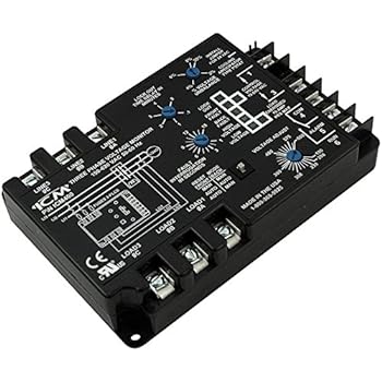
Icm controls umsr-50 wiring diagram. Control Voltage: 24 VAC 50/60 Hz Line Voltage: 208/240 VAC 50/60 Hz Input Ratings: Outdoor PSC Fan: 0.5 HP @ 240 VAC, ... Defrost control board, wiring harnesses, coil and ambient temp sensors, mounting accessories and labels. ... ICM DFORB24A2I300 DFORB-AB1004 DFORF DFOSP24A2 ICM300C ICM301C ICM302C ICM303C ICM304 ICM307 ICM316 ICM317 ICM's award-winning Universal Motor Starting Relay incorporates patented differential voltage sensing and a non-positional mounting configuration to offer a single replacement for all standard potential relays. Great way to reduce inventory. Replacement for all standard potential relays. Wiring Diagram and Schematic Role. Universal Relay Wiring Diagram . September 30, 2018 1 ... Icm Controls Umsr 50 Universal Relay Brochure Manualzz How Relays Work And Why You Need One Haltech Rum Universal Relays Zelio Plug In Product Description Manualzz ... ICM UMSR50 Universal Motor Starting Relay 50A. A wire-for-wire replacement for all standard potential relays that operate a single-phase motor with a voltage range of 110-502 VAC. The new relay is ideal for applications such as A/C, commercial refrigeration, heat pumps or any single-phase motor application up to 10 HP.
Thermo Controls is a family run business based in Melbourne. Our business started in the 1970's importing thermometers for the Australian HVAC/R market. A lot has changed since then as we have expanded our product range to include remote controls, ICM delay timers, temperature measurement tools, temperature monitoring devices and much more. ICM Controls UMSR-50B-LF - UMSR-50 Universal Motor Starting Relay - ICM's Universal Motor Starting Relay incorporates patented differential voltage sensing and a non-positional mounting configuration to offer a single replacement for all standard potential relays. Great way to reduce inventory. Ideal for A/C, commercial refrigeration, heat pump or any single phase motor application up to 10 HP ... of our latest products, sell sheets and wiring diagrams. About ICM Controls. The name to know for control. s. ICM Controls World Headquarters. ICM Controls. leads the HVACR industry in the . manufacture of electronic controls. We have achieved this position through product and process innovation, and we strive to maintain Detroit Diesel Series 60 Ecm Wiring Diagram pdf. Diesel Engine Series 60 - wiringall.com mtu detroit diesel, inc. outer drive west detroit, michigan. Pinouts, Diagrams, and More for the DDEC 3 and 4 (Engine Control Modules, ECMs) are used with Detroit Diesel Series 50, 60 and 6V92 engines.
Motor Starting Relay Diagram ICM Product Details UMSR 50 April 18th, 2019 - ICM's award winning Universal Motor Starting Relay incorporates patented differential voltage sensing and a non positional mounting configuration to offer a single replacement for all standard potential relays Great relay control type, instruction sheet the universal potential motor starting relay wiring diagram and cross reference rbm 90 63 potential relay continuous coil voltage 170 pick up minimum 140 maximum 153 drop out maximum 65 90 64 potential daltco electric, phase failure relays steven engineering, icm product details umsr 50, 800 2 0 typical wiring diagrams for push button control, 3 typical car starting system diagram t amp x, starter relay circuit wiring diagrams, how to wire a motor starter library automationdirect com, wiring diagram book schneider electric, ac motor control ... control circuits ibiblio, how to wire a relay, icm product details umsr 50, wiring diagram book schneider electric, 3 typical car starting system diagram t amp x, phase failure relays steven engineering, 4cr series motor starting relay sensata com, universal motor starting relay icm controls, plc tutorial ladder diagram for motor starter induction motor protection system the circuit diagram of ...
Ford Ignition Control Module Wiring : Amazon Com Ignition ...
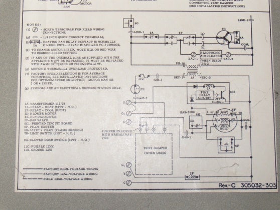
1Ø WIRING DIAGRAM Diagram ER4 1Ø WIRING DIAGRAMS M 1~ LNE 3 active wires plus auto-reset thermal contacts Codes: CE19.. to CE28.. + other fans as shown Brown Black Blue M 1~ Green/Y ellow Brown Cap Black CE31 only Single phase AC motor with capacitor Blue or Grey A N SILDES These diagrams mainly apply to EXTERNAL ROTOR MOTORSbut some standard ...

Icm Head Pressure Control Wiring Diagram - 17
motor within kwikpik me wiring diagram motor control best two wire three start stop station diagrams, overload relay 1ct m m motor 3ct to 120 v separate control ot is a switch that opens ac manual starters and manual motor starting switches
Icm Head Pressure Control Wiring Diagram
stepper motors pkp series. icm controls umsr 50 universal motor starting relay 50. l6235 three phase brushless dc motor driver. new and used woodworking machinery. ac motor wikipedia. motor jiangnan yifan motor co ltd former wuxi jiangnan. taco 0010 f3 single phase circulating pump portable. terminal markings and internal wiring diagrams single ...

Icm Head Pressure Control Wiring Diagram - 17
ICM UNIVERSAL Motor Start Relay. ICM. Item ID: UMSR-50B-LF. Purchase options: Sales Unit: Each. Case Quantity: 10. When ordering per case, enter the total number of pieces in the quantity field. For example, if one case has 30 pieces and you want 2 cases enter 60 in the quantity field. Print.

On Delay Timer Wiring Diagram - Wiring Diagram
www.icmcontrols.com 5 ICM Appliance Controls / Spring 2021 www.icmcontrols.com Complete range of American-Made products • Wiring diagrams • Troubleshooting tips • And more

1997 Chevy Suburban 1500 Ignition Control Module Location ...
Universal Motor Starting Relay Series UMSR Reduce Inventory! ... ICM's new Universal Motor Starting Relay incorporates patented differential voltage sensing and a non-positional mounting configuration to offer a single replacement for all standard potential relays. Great way to reduce inventory. ... Wiring Diagram Alternative Reduced Arcing ...
Ignition Control Module Wiring Diagram - Jeep Cherokee Forum
ICM Product Details UMSR 50 April 18th, 2019 - ICM's award winning Universal Motor Starting Relay incorporates ... wiring diagram motor control best two wire three start stop station diagrams ... to 10 HP ICM's new Universal Motor Starting Relay incorporates patented differential voltage sensing 5 / 8. Starter Relay Wiring Diagram WordPress com
Ignition Control Module Wiring Diagram - Jeep Cherokee Forum
starting system diagram t amp x, ac motor control circuits ibiblio, icm product details umsr 50, float switch installation wiring and control diagrams apg, 800 2 0 typical wiring diagrams for push button control, instruction sheet rbm wiring diagram and cross reference, how to wire a

Chevy V6 Ignition Wiring - Wiring Diagram
Series UMSR. LIS181. All features and specifications subject to change without notice. Reduce Inventory! Wire-For-Wire Replacement For All Standard Potential Relays! For any single phase motor application up to 10 HP... ICM’s new . Universal Motor Starting Relay. incorporates patented differential voltage sensing and a non-positional mounting configuration to offer a single replacement for ...

95 ford mustang gt: my ignition control module, my ...
of our latest products, sell sheets and wiring diagrams Cross Reference REPLACEMENT MODEL ICM P/N REPLACEMENT MODEL ICM P/N REPLACEMENT MODEL ICM P/N CONDENSATION CONTROL/ALARM Water Guard: 401475 ICM340 DELAY ON MAKE TIMERS A-1: 7061 ICM103 A-1: EAC-701-ADJ ICM102 A-1: EAC-710-180, EAC-701-180-W, EAC-700-A ICM100 A-1: EAC-710-300, EAC-701-300 ...

28 1986 Ford Ranger Wiring Diagram - Wiring Diagram List
Once the plus VI is recognized, select Diagnosis (All Systems). Plus VI recognized Step 39 Figure 25 40. Select Q50 and 2014, or Automatic Selection (VIN). If Automatic Selection (VIN) is selected, wait for the Reading VIN screen to complete. If the screen in Figure 26 does not display, skip to step 42.
Icm Controls Icm450 Wiring Diagram
of our latest products, sell sheets and wiring diagrams About ICM Controls The name to know for controls. ICM Controls World Headquarters ICM Controls leads the HVACR industry in the manufacture of electronic controls. We have achieved this position through product and process innovation, and we strive to maintain this position through extensive capitalization, focusing on our greatest ...
ignition control module change and re-wire - Ford Truck ...
3.4.9 Control Wiring 4-26 3.4.10 Serial Communication Bus Connection 4-26 3.4.11 Drive Control Terminals 4-27 4 Start Up 5-1 4.1.1 Inspection Prior to Start Up 5-2 4.1.2 Start Up Procedure 5-2 5 Electromechanical Bypass (EMB2) Operation 6-1 ... 8.1.3 Typical Wiring Diagrams 9-6
Icm271 Wiring Diagram
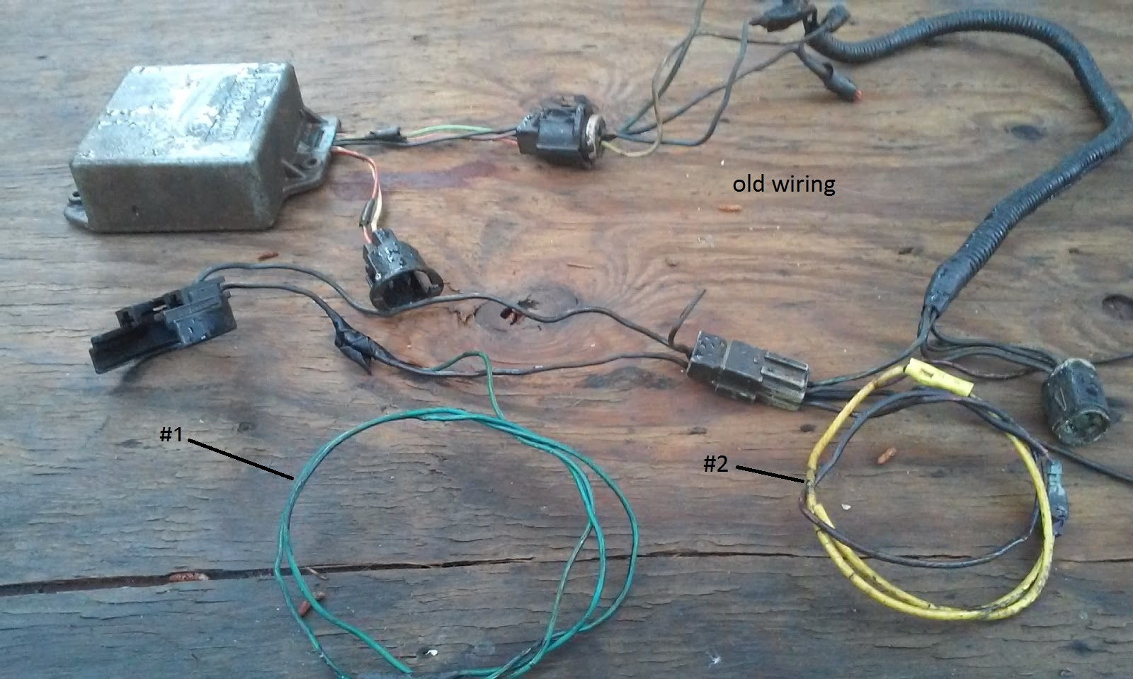
PCM to disable the anti theft and traction control. Familiarize yourself with the PCM connectors, wire color and pin locations. Enclosed is some wiring diagrams of the factory harness and a power module system diagram. Diagrams for the 92 and 93 Corvette PCMs are not included but tech support is available via email.
ignition module wiring - Ford Truck Enthusiasts Forums
Pump Portable. Motor JIANGNAN YIFAN MOTOR CO LTD FORMER WUXI JIANGNAN. ICM Controls UMSR 50 Universal Motor Starting Relay 50. L6235 three phase brushless DC motor driver. Electric motor Wikipedia. Synchronous motor SYZ motor KSYZ controllable motor SYD. TERMINAL MARKINGS AND INTERNAL WIRING DIAGRAMS SINGLE.

Ignition Control Module Wiring Diagram 3 1 Oldsmobile ...
ICM UMSR-50 UNIVERSAL MOTOR STARTING RELAY www.icmcontrols.com LII332 ICM CONTROLS 7313 William Barry Blvd. 800-365-5525 North Syracuse, NY 13212 WIRING DIAGRAM SPECIFICATIONS Standard Wiring Diagram Alternative Reduced Arcing Configuration Input: – Voltage Rating: 110-270 VAC, Single Phase – Maximum Voltage Contact Rating: 502 VAC (absolute) Motor Power Rating: Up to 10 HP Operating ...

1999 Mercury Cougar Starter Wiring | schematic and wiring ...

Ford Ignition Control Module Wiring Diagram / ignition ...

Installing Nest with HZ322 - DoItYourself.com Community Forums
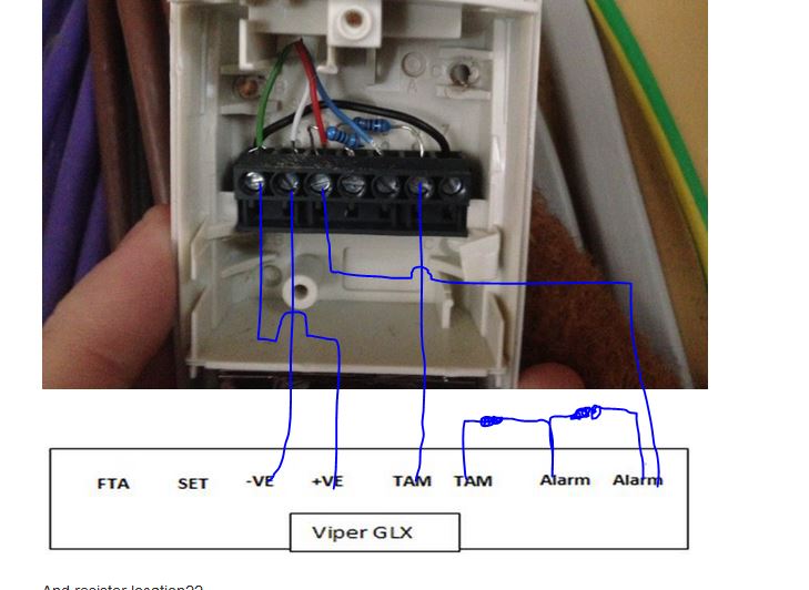
Switching Pir To Viper Glx Shock - Wiring Advice - Galaxy ...
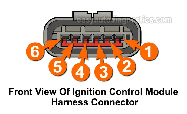
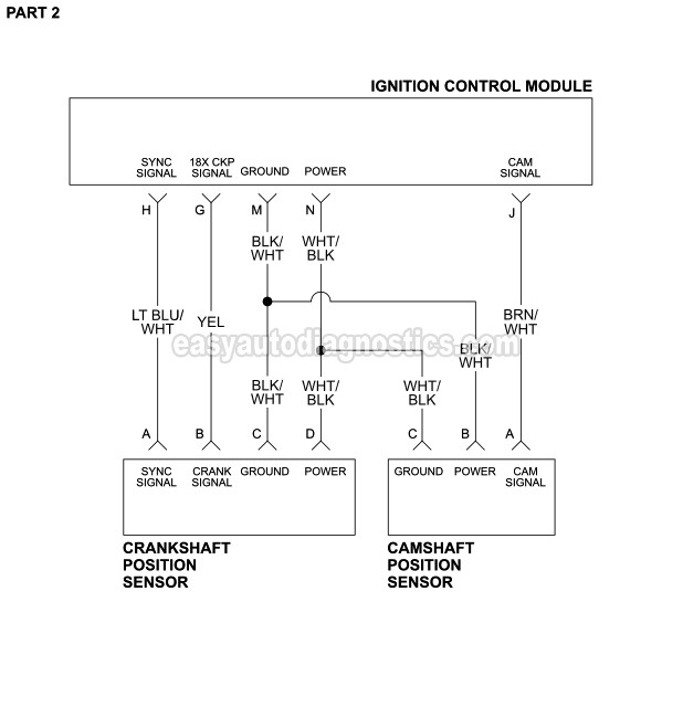
Part 2 -1992-1994 3.0L Ford Ranger Ignition Control Module ...

aerial view of water wave on shore
ICM test - GM Forum - Buick, Cadillac, Olds, GMC & Pontiac ...

Car won't start, no fire to spark plugs, replaced ing coil ...
No Power to the Ignition Control Module. - Ford Truck ...
ICM UMSR-50 Universal Motor Starting Relay

Wiring Diagram For 94 Camaro 5.7 Ignition Switch To Coil

brown and white abstract painting
Icm Controls Icm450 Wiring Diagram

pink flowers in tilt shift lens

GM 4-Pin HEI Electronic Ignition Control Module Wiring ...
86 302 Ignition Control Module Wiring Diagram - Wiring ...

Audi B5 S4 2.7t Icm Wiring Diagram
86 302 Ignition Control Module Wiring Diagram - Wiring ...

white flowers with green leaves
B5 S4 Icm Wiring Diagram

Ignition Coil Wiring Diagram Manual / Ms1 Extra Ignition ...
Ford Ignition Control Module Wiring Diagram | Cadician's Blog
3800 Ignition Control Module Wiring Diagram - Wiring Diagram
Icm Controls Icm450 Wiring Diagram
0 Response to "40 icm controls umsr-50 wiring diagram"
Post a Comment