43 bh-usa motor wiring diagram
Attention: If you are wiring a switch or motor to an exiting switch or motor and using the 2017 wiring guide, you will have to rewire the existing equipment to match the 2017 wiring guide in order for the new items to work. BOTH THE MOTOR AND THE SWITCH NEED TO BE REWIRED TO MATCH THE 2017 BH-USA Aug 05, 2016 · Directory List 1.0 - Free ebook download as Text File (.txt), PDF File (.pdf ) or read book online for free. Scribd is the world's largest social reading and publishing site. Open navigation menu
MOTOR BH-USA 110 Volt MOTOR MOTOR BLACK OR-2NGE GREEN HOT ROTATION ROTATION GROUND If a BH- USA by to ORANGE To reverse motor , swap switch orange and switch black Elite Motor s (230VAC) 115VAC PROCEDURE FOR 3/4 HP and 1 HP ELITE MOTOR S The following procedure is for wiring the pre-wired drum switch from BH-USA or the BH-USA wire harness to an ...
Bh-usa motor wiring diagram
Wiring From GEM Unit *To change motor direction, switch Motor Black & Motor Red wires. Note: drum switch Orange might be pre-wired to Motor Black*. GEM Orange needs to be on pin 2. ... If your motor has terminals inside, check for the motor diagram on the next page otherwise use the Standard T Numbered Wired motor drawing or the Standard color ... Dayton Electric Motor s Wiring Diagram – dayton 1 hp electric motor wiring diagram , dayton 1.5 hp electric motor wiring diagram , dayton electric motor wiring schematic, Every electric structure is composed of various distinct pieces. Each component ought to be set and linked to different parts in particular way. If not, the structure won’t work as it should be. Wiring Diagram Book A1 15 B1 B2 16 18 B3 A2 B1 B3 15 Supply voltage 16 18 L M H 2 Levels B2 L1 F U 1 460 V F U 2 L2 L3 GND H1 H3 H2 H4 F U 3 X1A F U 4 F U 5 X2A R Power On Optional X1 X2115 V ... MOTOR 3CT TO 120 V SEPARATE CONTROL * OT is a switch that opens when an overtemperature condition exists (Type MFO and MGO only) T1 T3 MOTOR 3 2 L2 T2 ...
Bh-usa motor wiring diagram. Technical Guides are PDF files that give more details on the product or installation of the product. They give valuable information on product. 2021 BH-USA Holiday & Shut-Down Schedule Orders placed may be delayed and not ship until 2022. I provide my contact information so BH Bikes can inform me about BH Bikes products and services which are tailored for me. I know that I can stop BH Bikes from communicating with me at any time. 1Ø WIRING DIAGRAM S (Form B) * Airflow direction base on left-hand blade installation. * Airflow direction base on left-hand blade installation. Airflow Airflow Airflow Airflow * * These diagram s are current at the time of publication, check the wiring diagram supplied with the motor . Inst Maint & Wiring _5.qxd 20/11/2015 11:37 AM Page 7 ELECTRIC MOTOR WIRING DIAGRAM DRUM SWITCH GFCI WARRANTY BH-USA assumes no responsibility or liability for installations and/or improper use of the equipment. This guide is intended to be used as a reference and general guideline only. BH-USA is not responsible for the design, construction or installation of docks, piers or lifts.
4.3 Wiring diagram main board Legend: Meaning Code Meaning Code Orientation: Right Orientation: Left PE Green / Yellow DISPLAY Display screen Display screen N / BU Blue RF Not applicable Not applicable L / BK Brown or Black VV Pre-heater Pre-heater WH White BYP Modulating by-pass actuator Modulating by-pass actuator RD Red M1 Exhaust motor ... Wiring Diagram Book A1 15 B1 B2 16 18 B3 A2 B1 B3 15 Supply voltage 16 18 L M H 2 Levels B2 L1 F U 1 460 V F U 2 L2 L3 GND H1 H3 H2 H4 F U 3 X1A F U 4 F U 5 X2A R Power On Optional X1 X2115 V ... MOTOR 3CT TO 120 V SEPARATE CONTROL * OT is a switch that opens when an overtemperature condition exists (Type MFO and MGO only) T1 T3 MOTOR 3 2 L2 T2 ... Dayton Electric Motor s Wiring Diagram – dayton 1 hp electric motor wiring diagram , dayton 1.5 hp electric motor wiring diagram , dayton electric motor wiring schematic, Every electric structure is composed of various distinct pieces. Each component ought to be set and linked to different parts in particular way. If not, the structure won’t work as it should be. Wiring From GEM Unit *To change motor direction, switch Motor Black & Motor Red wires. Note: drum switch Orange might be pre-wired to Motor Black*. GEM Orange needs to be on pin 2. ... If your motor has terminals inside, check for the motor diagram on the next page otherwise use the Standard T Numbered Wired motor drawing or the Standard color ...
No.ISSN: 2722-1318 JUDUL; Susunan Redaksi ...
Design Guide

Applied Sciences | Free Full-Text | Optimal Design of a Six ...

Dynamic Modeling and Control Strategy Optimization for a ...
SNIKO 2018

3G3AX-(MX2,RX)-ECT Manual Datasheet by Omron Automation and ...
EQUIPMENT GUIDE

Wiring Smith & Jones Motor for 115v

Energies | Free Full-Text | Energy Saving Approach for an ...

Pertemuan Ilmiah Tahunan Fetomaternal 19
SISTEM MANAJEMEN KESELAMATAN DAN KESEHATAN KERJA (SMK3) PADA ...
Multi-turn actuators SA 07.2 – SA 16.2 SAR 07.2 – SAR 16.2 ...
AUTOMA TIC CONTROLS

A new wireless charging system for electric vehicles using ...
No.ISSN: 2722-1318 JUDUL; Susunan Redaksi ...
PERANCANGAN SISTEM PLAMBING DI PESANTREN AR-RAUDLATUL HASANAH ...
No.ISSN: 2722-1318 JUDUL; Susunan Redaksi ...
Downloads | Product & Technical Documents | ZIEHL-ABEGG
Photovoltaic system - Wikipedia
800-259-8715 WWW.BH-USA.COM
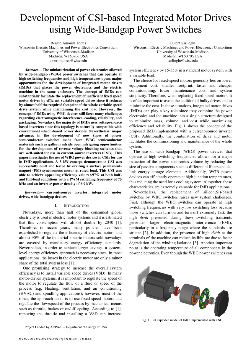
PDF) Development of Current-Source-Inverter-based Integrated ...

Fujitsu Rom18la2 | PDF | Hvac | Air Conditioning

3G3AX-(MX2,RX)-ECT Manual Datasheet by Omron Automation and ...
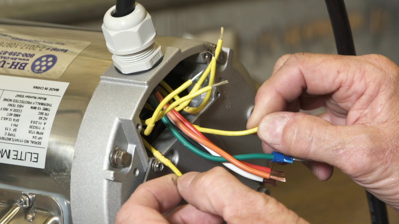
Elite Motors - Stainless Steel C-Face Boat Lift Motor - 110v Wiring
Untitled
Part-turn actuators SGC 04.1 – SGC 12.1 SGCR 04.1 – SGCR 12.1 ...
Untitled
ISSN 2528 - 5114
Prosiding

Technical support FAQ - Simu
EQUIPMENT GUIDE
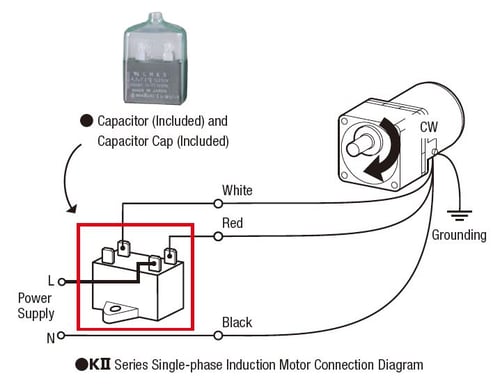
What Does a Capacitor Do?
EQUIPMENT GUIDE

Leeson/EG 1 1/2 HP Stainless C-Face Electric Motor - BH-USA
Untitled
EDISI BAHASA INDONESIA
FA PRODUCT CATALOG
800-259-8715 WWW.BH-USA.COM

Marathon Motors - 3/4 HP 56 Frame Boat Lift Motor - 110v Wiring
Applied Sciences | Free Full-Text | Actuator Weak Fault ...
Delta Classical Field Oriented Control AC Motor Drive C2000 ...

Thermo-sensitive electroactive hydrogel combined with ...
Elite Motors (115VAC) to BH-USA switch and harness Elite ...
0 Response to "43 bh-usa motor wiring diagram"
Post a Comment